Optical Fiber Technology: Principles, History, and Applications
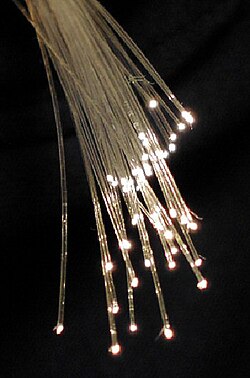
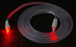
An optical fiber is a flexible filament made of glass or plastic designed to transmit light from one end to the other. Unlike traditional electrical cables, these fibers allow for data transmission over significantly longer distances and at much higher bandwidths. Because they use light rather than electricity, optical fibers are immune to electromagnetic interference and experience far less signal loss.
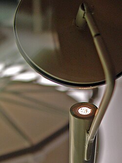
Beyond telecommunications, these fibers are essential for illumination, medical imaging (such as fiberscopes), and specialized industrial tools like fiber lasers and sensors.
Key Facts
- Core Principle: Operates via total internal reflection, acting as a waveguide for light.
- Material: Primarily composed of high-purity silica glass or plastic.
- Speed: Signals typically travel at approximately 200,000 kilometers per second.
- Types: Divided into single-mode (long distance) and multi-mode (short distance/high power).
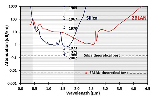
- Efficiency: Modern low-loss fibers can achieve attenuation as low as 0.1400 dB/km.
How Optical Fibers Work
The Refractive Index
The refractive index measures the speed of light within a material. Light travels fastest in a vacuum (approximately 300,000 km/s), which is defined as having a refractive index of 1. In a typical telecommunications fiber, the cladding (outer layer) is made of pure silica with an index of 1.444, while the core is made of doped silica with a slightly higher index of 1.4475. The higher the index, the slower the light travels.
Total Internal Reflection
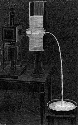
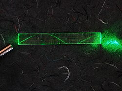
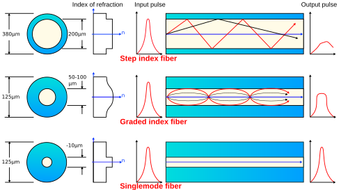
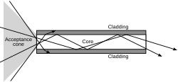
Light is trapped within the core through a phenomenon called total internal reflection. Because the core has a higher refractive index than the surrounding cladding, light hitting the boundary at a specific angle is reflected back into the core rather than escaping. This allows the fiber to act as a waveguide, guiding light over vast distances.
Single-Mode vs. Multi-Mode Fibers
Fibers are categorized by the number of paths, or modes, that light can take as it propagates:
- Multi-mode fibers: These have a wider core diameter, supporting multiple propagation paths. They are ideal for short-distance links and applications requiring high power transmission.
- Single-mode fibers (SMF): These have a much narrower core, supporting only a single mode of light. They are used for most communication links exceeding 1,050 meters (3,440 ft) due to their lower signal degradation.
Evolution and History
The foundation of fiber optics began in the early 1840s when Daniel Colladon and Jacques Babinet demonstrated light guiding by refraction in Paris. This was later popularized in London by John Tyndall. However, practical data transmission didn't arrive until 1965, when physicist Manfred Börner demonstrated the first working system at Telefunken Research Labs.
A major turning point occurred in 1983 when chemical engineer Thomas Mensah joined Corning. He increased the manufacturing speed of high-quality fibers from two meters per second to over 50 meters per second, making optical cables more cost-effective than copper. This innovation accelerated the deployment of metropolitan networks, such as the first one in Turin in 1977.
Materials and Manufacturing
Common Materials
Most modern fibers use silica glass due to its excellent transparency. Other specialized materials include:
- Fluoride Glass (ZBLAN): Offers very low attenuation but is fragile, moisture-sensitive, and difficult to manufacture without crystallization.
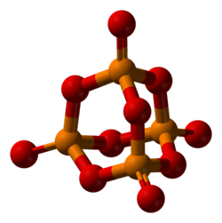
- Phosphate and Chalcogenide Glass: Used for specific industrial or sensing applications.
The Production Process
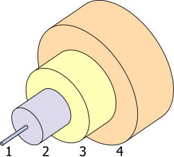
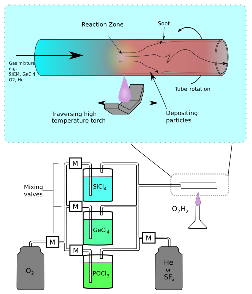
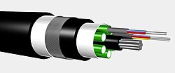
Glass fibers are typically created through a process called drawing, where a preform (a thick rod of glass) is heated and pulled into a thin strand. Plastic fibers may be drawn or extruded. To protect the fragile glass, fibers are encased in a buffer and a protective outer jacket.
Signal Loss and Attenuation
Attenuation refers to the loss of signal strength as light travels through the fiber. In silica fibers, this is primarily caused by two factors:
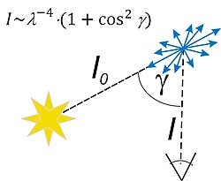
- Rayleigh Scattering: The dominant loss mechanism at telecommunications wavelengths, caused by microscopic variations in the glass.
- Absorption: Caused by impurities or the intrinsic properties of the glass (infrared absorption), which increases sharply above 1570 nm.
To combat this, researchers developed the erbium-doped fiber amplifier in the mid-1980s, which allowed signals to be boosted without needing to convert them from optical to electrical and back again.
![Experimentally measured spectral attenuation of silica core optical fiber.[74] Minimum attenuation is 0.1400 dB/km at 1560 nm wavelength.](/images/9e/c5/9ec56c9712ccc83cc6fd589e8f779c1c2077b9e2e894cc79aa60c33241c04cdd.jpg)
Summary of Fiber Types
| Feature | Single-Mode Fiber (SMF) | Multi-Mode Fiber (MMF) |
|---|---|---|
| Core Diameter | Small (approx. 8 μm) | Large |
| Distance | Long-haul (> 1,050m) | Short-distance |
| Light Paths | Single path | Multiple paths |
| Primary Use | Telecommunications/Internet | Local networks/High power |
Frequently Asked Questions
![Dispersion orders of fused silica. GDD: Group delay dispersion, TOD: 3rd-order dispersion, FOD: 4th order, FiOD: 5th order, SiOD: 6th order, SeOD: 7th order, EOD:8th order, NOD: 9th order, TeOD: 10th order[107][108]](/images/94/90/94907fda6ca3216ad4837df63097e78bf44a1c66c54632ba231d21e8716026b1.png)
Why is optical fiber better than copper cable?
Optical fibers provide significantly higher bandwidth, lower signal loss (attenuation), and are completely immune to electromagnetic interference, which often plagues electrical copper cables.
How fast does data travel through an optical fiber?
While light in a vacuum travels at 300,000 km/s, the refractive index of the glass slows it down. In practice, signals in an optical fiber travel at approximately 200,000 kilometers per second.
What is the difference between the core and the cladding?
The core is the inner center of the fiber where light travels. The cladding is the outer layer surrounding the core; it has a lower refractive index, which forces the light to reflect back into the core via total internal reflection.
What causes signal loss in fiber optics?
Signal loss is primarily caused by Rayleigh scattering (light bouncing off microscopic density fluctuations) and absorption (where the material or impurities absorb the light energy).
What are some non-communication uses for fiber optics?
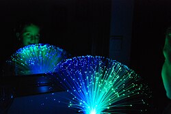
Fibers are used in medical imaging (fiberscopes), decorative lighting, fiber optic sensors for industrial monitoring, and high-power fiber lasers.