Microwave Relay Systems: The Evolution of Long-Distance Telephony
Before the era of fiber optics and satellites, the backbone of global communication relied on the invisible beams of microwave relay systems. These systems revolutionized how voice and video data traveled across continents, moving telephony from the limitations of physical wires and low-frequency radio to the high-bandwidth potential of the gigahertz spectrum.
The Path to High-Frequency Communication
The journey toward microwave communication began with early radio telephone experiments in 1915, following AT&T's acquisition of Lee de Forest's audion vacuum tube patents. Initial links between Virginia, Hawaii, and Paris paved the way for a permanent New York-to-London connection in 1927. This early system operated at 60 kHz, utilizing the Earth's curvature to achieve over-the-horizon performance.
By the late 1920s, researchers began exploring megahertz frequencies, discovering that ionospheric scatter (the reflection of radio waves off the ionosphere) could enable long-distance propagation. However, the unpredictable nature of this scattering caused interference, driving the need for higher frequencies and greater bandwidth.
Progress continued through the 1930s and early 1940s, with a 60 MHz link established between Boston and Cape Cod in 1934, and a 150 MHz system at Chesapeake Bay in 1941. The latter was capable of multiplexing 12 telephone calls on a single connection. While Bell Labs envisioned a future in the gigahertz range using horn antennas, the onset of World War II shifted the focus toward military applications.
The Birth of Microwave Systems
The technological breakthroughs of World War II—specifically the cavity magnetron, improved klystrons, waveguides, and crystal detectors—provided the necessary tools for microwave radiotelephony. The UK pioneered this with the Wireless Set No. 10 (WS.10), which multiplexed eight calls and was used extensively during the Normandy landings to maintain links between forward units and UK headquarters.
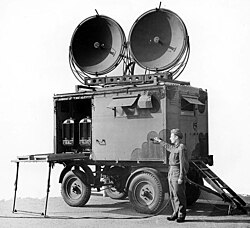
In the United States, Bell Labs experimented with frequencies of 3, 4.6, and 9.5 GHz. By 1944, AT&T began planning an intercity telephony system. While the company initially considered installing thousands of miles of coaxial cable, engineering studies revealed that microwave relays were more cost-effective to install, making them the preferred choice for rapid expansion.
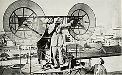
During this period, researchers discovered tropospheric scatter—the phenomenon where UHF signals travel further than theoretically possible—which led to the FCC's "television freeze" of 1948 as the government worked to reallocate frequencies.
From Prototype to National Network: TDX and TD-2
While awaiting FCC frequency allocations, Bell developed the TDX line, an experimental prototype between New York and Boston. Completed in 1947, it used frequency modulation to carry four 10 MHz channels and supported early experimental television transmissions.
The success of TDX led to the TD-2 system, a production-grade network designed for nationwide use. The New York-to-Chicago route served as the blueprint. To minimize line losses (the loss of signal strength as it travels through a cable), early stations were built as tall concrete towers with electronics housed mid-way up the structure.
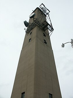
The TD-2 system officially opened for service on September 1, 1950, between New York and Chicago, followed shortly by a link between Los Angeles and San Francisco. By September 1951, these links allowed the nationwide broadcast of President Harry S. Truman's address at the Treaty of San Francisco.
Technological Refinements and the TH System
Throughout the 1950s and 60s, AT&T focused on reliability and capacity. Key improvements included:
- Tube Longevity: The 416A transmitter tube's lifespan increased from 2,000 hours in 1950 to 20,000 hours by 1967.
- Slot Filters: The introduction of ferrite-core slot filters in 1951 allowed for narrower channel spacing and more precise antenna pointing.
- Rapid Switching: A standby channel system was implemented to prevent signal drops during equipment failure.
In 1955, Bell Labs developed the TH system, operating in the 6 GHz band. TH utilized polarization to separate signals, allowing for 1,200 calls per channel. This led to the adoption of horn antennas, which preserved polarization and allowed existing TD-2 sites to be upgraded, increasing their capacity to 600 calls per channel.
By 1962, the system evolved into TD3, a solid-state system utilizing travelling-wave tubes and Schottky barrier diodes. By 1968, TD-2 and its successors carried 40% of all U.S. long-distance traffic and 95% of inter-city television signals.
The Transition to Fiber and Satellites
The decline of microwave relay systems began in 1970 due to two primary technological shifts:
- Geostationary Satellites: Satellites became the more efficient method for distributing television signals from a single studio to multiple local stations.
- Optical Fiber: The development of high-quality optical fiber by Corning Glass and the room-temperature semiconductor laser by Bell Labs enabled pulse-code modulation (PCM) signals to travel with far lower loss.
By the early 1980s, fiber optics had largely replaced microwave systems. AT&T eventually sold off its towers in 1999, leaving many to stand derelict.
Modern Reemergence: The Latency Advantage
Interestingly, some former TD-2 towers have been repurposed for high-frequency trading and specialized data links. This is due to latency—the delay in data transmission. Signals travel faster through the air (approximately 299,700 km/s) than through glass fiber (approximately 200,000 km/s). Additionally, microwave links provide a straighter point-to-point path than fiber cables, which must follow existing infrastructure like railways.
In 2011, measurements on the New York-to-Chicago link showed a latency drop of 2.5 milliseconds, prompting a resurgence of microwave technology for time-sensitive data transmission.
Key Facts
- First Microwave Link: The UK's Wireless Set No. 10 (WS.10) was the world's first microwave relay telephone system.
- TD-2 Capacity: Originally designed for telephone and TV, it eventually carried 95% of U.S. inter-city TV signals by 1968.
- Speed Advantage: Microwave signals travel at nearly the speed of light in a vacuum, significantly faster than signals in optical fiber.
- Infrastructure: Early towers were concrete to house electronics near antennas; later towers shifted to steel.
- Frequency Shift: Systems moved from kHz to MHz, and finally to GHz to increase bandwidth and reduce interference.
| System | Primary Frequency | Key Technology | Capacity/Feature |
|---|---|---|---|
| TDX | 3.9 - 4.4 GHz | Frequency Modulation | Experimental Prototype |
| TD-2 | 3.7 - 4.2 GHz | Concrete Towers / Klystrons | 480 calls per channel |
| TH | 6 GHz | Signal Polarization / Horn Antennas | 1,200 calls per channel |
| TD3 | Various | Solid State / Travelling-wave tubes | 1,200 calls per channel |
Frequently Asked Questions
Why were early microwave towers made of concrete?
Concrete towers allowed the radio electronics to be housed mid-way up the tower, placing them as close to the antennas as possible to avoid signal loss in the transmission lines.
What is tropospheric scatter?
Tropospheric scatter is a phenomenon where UHF signals are detected at ranges far beyond what standard line-of-sight theory suggests is possible, allowing for longer-range communication.
Why did AT&T switch from microwave relays to fiber optics?
Fiber optics offered significantly higher quality, lower signal loss, and the ability to carry massive amounts of data using semiconductor lasers and pulse-code modulation.
Why are microwave towers being used again today?
They are used for high-speed data transmission because signals travel faster through air than through fiber optic glass, and the point-to-point paths are straighter, reducing latency.
How did the TH system increase capacity over the TD-2?
The TH system used polarization to separate signals, which allowed channels to operate closer together in frequency and utilize the available bandwidth more efficiently.