Vibration Analysis: Principles of Mechanical Resonance and Modal Analysis
Vibration Analysis (VA) is a critical diagnostic tool used in industrial and maintenance environments to detect equipment faults, reduce maintenance costs, and minimize downtime. As a cornerstone of condition monitoring (CM)—often referred to as predictive maintenance (PdM)—VA is primarily employed to identify issues in rotating machinery, such as fans, motors, pumps, and gearboxes. Common faults detected include imbalance, misalignment, resonance conditions, and rolling element bearing failures.
To analyze these vibrations, engineers measure displacement, velocity, and acceleration. While these are initially captured as a time waveform (TWF), they are most commonly converted into a frequency spectrum using a fast Fourier transform (FFT). This spectrum allows technicians to pinpoint specific faulty components by analyzing their unique frequency signatures.
Key Facts
- VA is used for predictive maintenance to detect imbalance, misalignment, and bearing faults.
- The natural frequency of a system is determined by its mass and stiffness.
- Damping dissipates energy, causing vibrations to decay over time.
- Resonance occurs when the forcing frequency matches the system's natural frequency.
- Fourier transforms convert time-domain signals into the frequency domain for easier analysis.
- Mode shapes describe the physical deformation of a system at specific natural frequencies.
Foundations of Free Vibration
Undamped Free Vibration
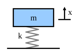
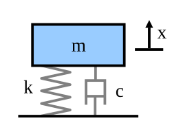
In its simplest form, a vibration system can be modeled as a mass attached to a spring. In an undamped system, the restoring force is proportional to the displacement (Hooke's Law: $F_s = -kx$). The resulting motion is a simple harmonic oscillation where the mass moves forever at a constant magnitude.
The natural frequency ($f_n$) is defined by the relationship between stiffness ($k$) and mass ($m$):
$f_n = \frac{1}{2\pi} \sqrt{\frac{k}{m}}$
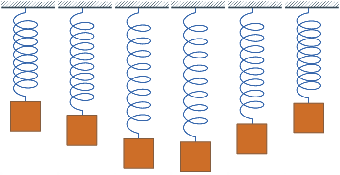
From an energy perspective, this motion is a continuous exchange between potential energy (stored in the stretched or compressed spring) and kinetic energy (the energy of the moving mass). When the spring is released, potential energy converts to kinetic energy, which then converts back to potential energy as the spring compresses.
Damped Free Vibration
Real-world systems always experience damping, which is the dissipation of energy that eventually brings the system to rest. Damping is represented by a damping coefficient ($c$), creating a force proportional to velocity ($F_d = -cv$).
The damping ratio ($\zeta$) determines how the system "rings down." For example, metal structures like engine crankshafts or airplane fuselages typically have very low damping factors (less than 0.05), whereas automotive suspensions are designed with higher damping ratios (0.2–0.3) to stabilize the vehicle.
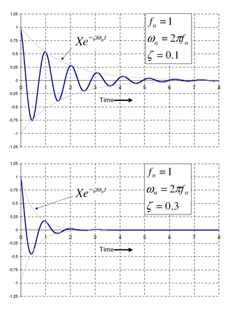
While damping slightly lowers the natural frequency (creating the damped natural frequency, $f_d$), the difference is often negligible in practical applications. For a system with a 0.1 damping ratio, the damped frequency is only 1% lower than the undamped frequency.
Forced Vibration and Resonance
Forced vibration occurs when an external periodic force is applied to the system. The resulting amplitude of vibration depends on the frequency ratio ($r$), which is the ratio of the forcing frequency ($f$) to the natural frequency ($f_n$).
- When $r \ll 1$: The vibration is in phase with the force, and the amplitude is close to the static deflection (the displacement caused by a constant force).
- When $r = 1$: The system is at resonance. Regardless of the damping level, the vibration is 90 degrees out of phase with the forcing frequency, often resulting in maximum amplitude.
- When $r \gg 1$: The vibration is 180 degrees out of phase with the forcing frequency.
Complex Forcing Functions and Frequency Response
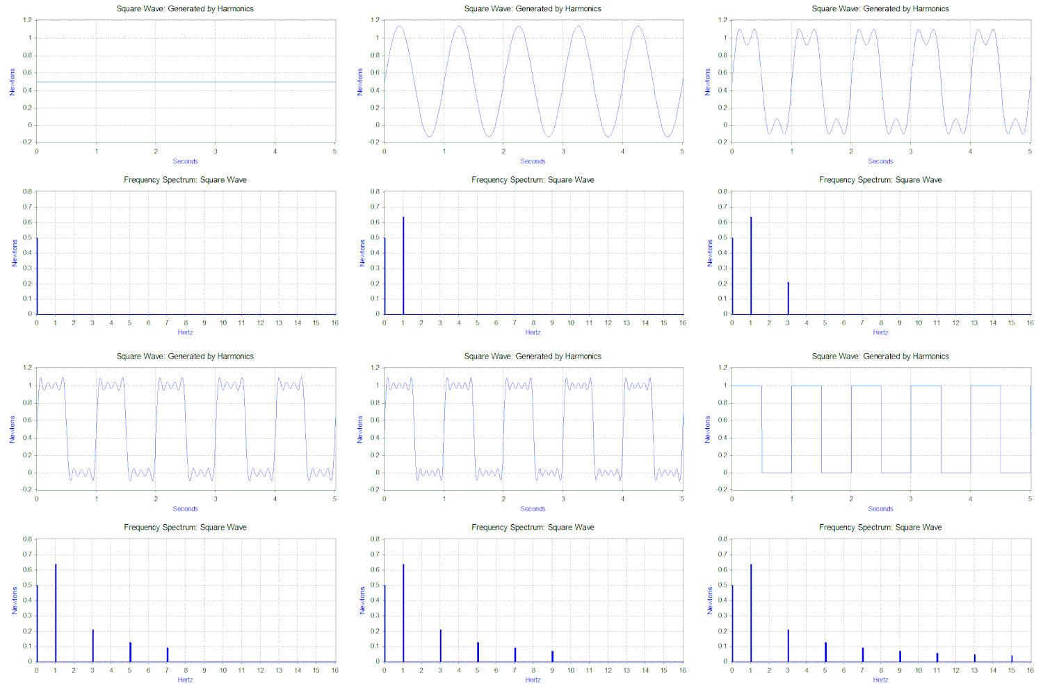
Not all forces are simple sine waves. Complex forces, such as a 1 Hz square wave, can be broken down into a sum of sine waves (harmonics) using the Fourier transform. This means a square wave is actually composed of a constant force (0 Hz) and a series of odd-frequency harmonics.
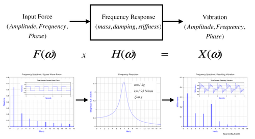
The Frequency Response Function (FRF) describes how the system responds to these different frequencies. If one of the harmonics of a complex input force matches the system's natural frequency, the system will output a high vibration at that frequency, even if the input energy at that specific harmonic was relatively low.
Multiple Degrees of Freedom (MDOF) and Modal Analysis
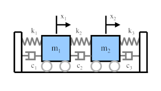
Complex machinery cannot be modeled by a single mass and spring; they have multiple degrees of freedom (MDOF). These systems are analyzed using matrices for mass $[M]$ and stiffness $[K]$.
The Eigenvalue Problem
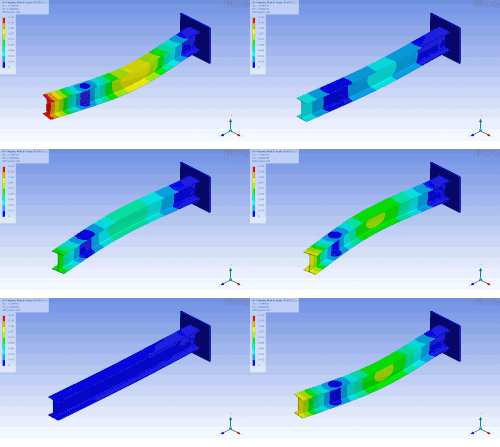
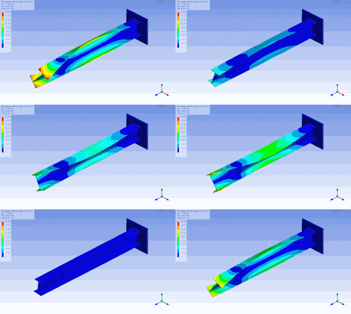
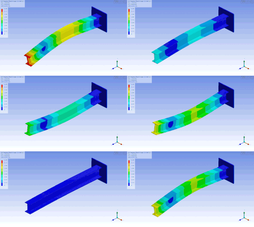
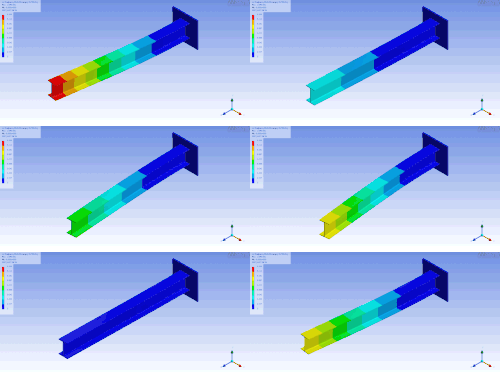
To find the natural frequencies of an MDOF system, engineers solve an eigenvalue problem. The resulting eigenvalues provide the natural frequencies, while the eigenvectors define the mode shapes—the specific patterns of deformation the system takes at each natural frequency.
For a simple 2-DOF system with two 1 kg masses and three 1000 N/m springs, the natural frequencies are calculated as 5.033 Hz and 8.717 Hz, each with a distinct mode shape.
Visualization and Finite Element Method (FEM)
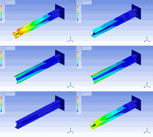
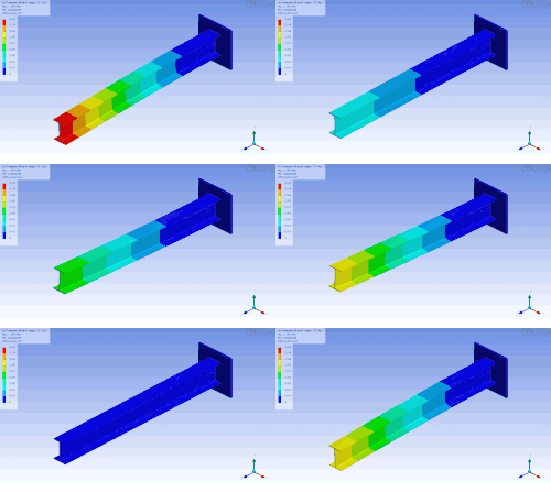
For systems with hundreds of degrees of freedom, such as a cantilevered I-beam, software like ANSYS or Femap is used. The finite element method (FEM) meshes the object into small elements to approximate the mass and stiffness matrices. While these models generate many frequencies, usually only the first few modes are critical for practical engineering applications.
Simplifying MDOF to SDOF
Through the property of orthogonality, a complex MDOF system can be mathematically converted into a set of independent single-degree-of-freedom (SDOF) equations. This allows engineers to analyze the response of each mode separately, simplifying the overall analysis of the structure.
| Parameter | Undamped System | Damped System | Forced System (Resonance) |
|---|---|---|---|
| Energy State | Constant exchange (K $\leftrightarrow$ P) | Gradual dissipation | Energy added by external force |
| Amplitude | Constant | Decaying (Ringing down) | Maximum at $r=1$ |
| Frequency | Natural Frequency ($f_n$) | Damped Natural Frequency ($f_d$) | Forcing Frequency ($f$) |
| Phase | N/A | N/A | 90° shift at resonance |
Frequently Asked Questions
What is the difference between natural frequency and damped natural frequency?
Natural frequency is the frequency at which a system oscillates without any damping or external force. Damped natural frequency is the actual frequency of oscillation when damping is present, which is slightly lower than the undamped natural frequency.
How does a Fourier transform help in vibration analysis?
A Fourier transform converts a time-domain signal (a waveform) into a frequency-domain spectrum. This allows analysts to see which specific frequencies are present in the vibration, making it possible to identify which component (e.g., a specific bearing or gear) is failing.
What happens during mechanical resonance?
Resonance occurs when the frequency of an external forcing function matches the natural frequency of the system. This leads to a significant increase in vibration amplitude, which can cause structural damage if not controlled.
What are mode shapes in MDOF systems?
Mode shapes are the specific geometric patterns of displacement that a structure assumes when vibrating at one of its natural frequencies. They are mathematically represented as eigenvectors.
Why is the damping ratio important for automotive suspensions?
Automotive suspensions require a higher damping ratio (typically 0.2–0.3) compared to structural metals to ensure that vibrations from the road dissipate quickly, providing stability and comfort for the passengers.