HFC Networks: Architecture, Evolution, and the Shift to Distributed Access
A Hybrid Fiber-Coaxial (HFC) network is a broadband telecommunications architecture that combines optical fiber and coaxial cable to deliver high-speed data, television, and voice services. By leveraging the long-distance efficiency of fiber optics and the established reach of coaxial cabling, cable operators can provide robust connectivity to thousands of homes from a centralized location.
The HFC Network Hierarchy
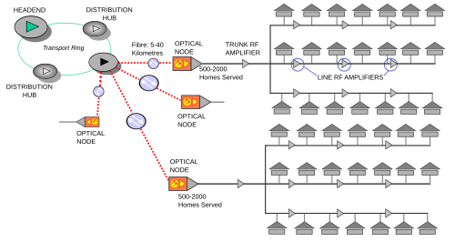
The journey of a signal begins at the master headend, the primary control center of the network. This facility typically houses satellite dishes for receiving distant video signals, IP aggregation routers for internet traffic, and telephony equipment. In HFC environments, voice services are delivered via PacketCable, a standard for VoIP over cable networks.
From the master headend, the network may extend to regional headends or hubsites. These local facilities customize the service by adding Public, Educational, and Government (PEG) channels or inserting targeted local advertising. They also integrate internet services using a Cable Modem Termination System (CMTS) or a Converged Cable Access Platform (CCAP), which combines both internet and video functionality into a single system.
Signal Modulation and Processing
To prepare content for transmission, video is encoded using standards such as MPEG-2, DVB-C, or NTSC. Edge QAMs (Quadrature Amplitude Modulation) are used to convert digital video sources into RF signals suitable for coaxial transmission. In modular CMTS architectures, Edge QAMs can also handle internet data.
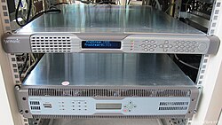
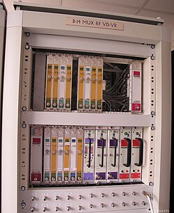
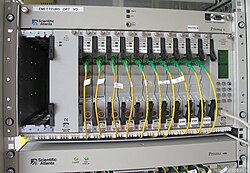
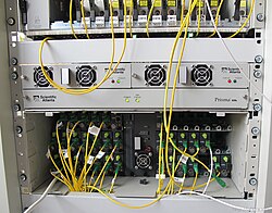
These various services—data from the CMTS/CCAP and video from the QAM modulators—are merged into a single RF electrical signal using RF management modules like splitters and combiners. This combined signal is then fed into a broadband optical transmitter, often housed in platforms such as the Cisco Prisma II or Arris CH3000.
![CMTS provides internet on an HFC network and has RF connections on the rear [22]](/images/31/c4/31c44377942553611e21cfe301dcf63aa0eb726141cf0ed478d28405fadbbdf2.jpg)
From Fiber to the Home
The optical transmitter converts the electrical RF signal into an optically modulated downstream signal. This signal travels through fiber optic cables in point-to-point, star, or protected ring topologies to reach the fiber optic node.
The node acts as the bridge between the optical and coaxial worlds. It contains a broadband optical receiver that converts the light signal back into an electrical RF signal (typically ranging from 50 MHz to 1000 MHz). Simultaneously, the node uses a return-path transmitter to send customer data back to the headend, typically using a frequency range of 5–42 MHz in North America or 5–65 MHz elsewhere.
The Coaxial Distribution Plant
Once the signal leaves the node, it enters a coaxial trunk, which serves between 25 and 2,000 homes (with 500 being typical). Because electrical signals lose strength over distance (attenuation), trunk amplifiers are placed at intervals to boost the signal. To avoid needing individual power sources for every amplifier and node, AC power (60V or 90V) is injected directly into the coaxial line via power inserters.
The network then branches into smaller distribution cables. Bridgers and distribution amplifiers (or line extenders) further manage the signal as it moves down individual streets. Finally, RF taps connect the distribution line to the individual drop—the final coaxial cable that enters the customer's home via an F-connector.
Key Facts
- Topology: Combines fiber optics for long-haul transport and coaxial cable for the "last mile."
- Node Capacity: A single optical node typically serves 25 to 2,000 homes.
- Frequency Ranges: Downstream signals typically range from 50 MHz to 1 GHz; upstream ranges from 5 MHz to 42/65 MHz.
- Powering: AC power is transmitted through the coaxial cable to power active components like amplifiers.
- Hardware Evolution: Transition from silicon to GaAs (Gallium Arsenide) and then GaN (Gallium Nitride) transistors enabled spectrum expansion up to 1.2 GHz.
Evolution and Modernization
HFC networks have evolved to increase bandwidth and reduce noise. A major shift is the move toward Distributed Access Architecture (DAA), which includes Remote PHY and Remote MACPHY. In traditional HFC, the headend performs RF modulation; in Remote PHY, the modulation happens at the node (the Remote PHY Device or RPD), allowing the fiber to carry digital 10 Gigabit Ethernet signals instead of analog signals.
This transition eliminates the need for frequent manual calibration, reduces maintenance costs, and enables higher-order modulation like 4096 QAM. Furthermore, Virtual CCAPs (vCCAPs) allow operators to run network management software on standard x86 servers, increasing flexibility and capacity.
| Technology | Primary Function | Key Advantage |
|---|---|---|
| CMTS | Internet data management | Centralized control of cable modems |
| CCAP | Combined Data and Video | Reduced equipment footprint |
| Remote PHY | Digital fiber transport | Better signal quality; no analog fiber |
| Remote MACPHY | Distributed DOCSIS protocol | Lower latency than Remote PHY |
| n+0 Architecture | Node-to-home (no amps) | Maximum speed; minimal noise |
Frequently Asked Questions
What is the difference between a CMTS and a CCAP?
A CMTS (Cable Modem Termination System) specifically handles internet data. A CCAP (Converged Cable Access Platform) is a more modern evolution that integrates both the CMTS data functions and the Edge QAM video functions into a single chassis.
How does power reach the amplifiers on utility poles?
Power is delivered through the coaxial cable itself. Power supplies and inserters add 60V or 90V AC to the line, allowing nodes and amplifiers to operate without needing a separate electrical connection at every pole.
What is the purpose of a fiber optic node?
The node acts as a converter. It transforms the downstream optical signals from the headend into electrical RF signals for coaxial distribution and converts the upstream electrical signals from customers back into optical signals for the return trip.
How does Remote PHY improve internet quality?
Remote PHY replaces analog optical signals with digital signals (like 10GbE) and moves the RF modulation to the node. This reduces signal degradation, eliminates the need for bi-annual network calibration, and allows for more efficient data modulation (e.g., 4096 QAM).
What is an "n+0" architecture?
An n+0 architecture is a design where there are zero amplifiers between the optical node and the customer's home. By reducing the service group size (e.g., to 128 subscribers), operators can significantly increase internet speeds and reliability.