Airfoil Aerodynamics: Principles of Lift, Drag, and Design
An airfoil (or aerofoil in British English) is a streamlined body specifically designed to generate significantly more lift than drag. While most commonly associated with aircraft wings, airfoils are essential components in sails and propeller blades. When these same principles are applied to bodies submerged in water, they are referred to as hydrofoils.
The fundamental mechanism of an airfoil involves deflecting a fluid as the body moves through it. When oriented at a suitable angle, this deflection creates an aerodynamic force. This force is divided into two primary components: lift, which acts perpendicular to the freestream velocity, and drag, which acts parallel to it.
Key Facts
- Lift Generation: Primarily driven by the angle of attack, though cambered airfoils can generate lift even at a zero-degree angle.
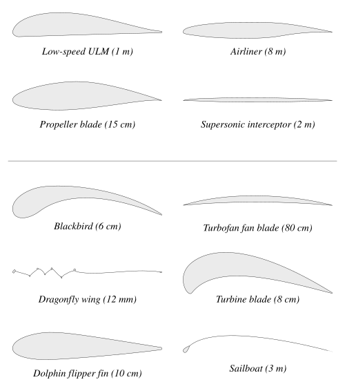
- Speed Optimization: Subsonic airfoils typically feature rounded leading edges, whereas supersonic designs are slimmer and more angular.
- Stall Point: Occurs when the angle of attack becomes too steep (typically 10° to 15°), causing the boundary layer to separate and lift to drop sharply.
- Laminar Flow: Reducing skin friction drag by moving the maximum thickness point further back along the chord.
- Critical Components: All functional airfoils require a sharp trailing edge to maintain well-defined lift.
Airfoil Geometry and Terminology
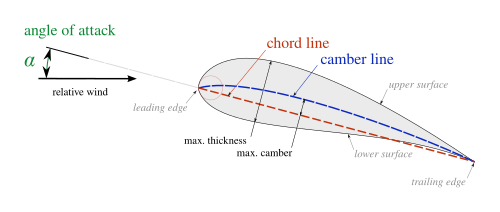
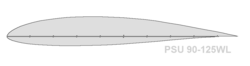
To analyze how an airfoil performs, engineers use a specific set of geometric definitions. The leading edge is the front-most point with the maximum curvature, while the trailing edge is the furthest point from the front.
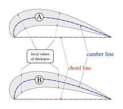
The straight line connecting these two points is called the chord line, and its length is the chord. The shape is further defined by camber (the curvature of the airfoil) and thickness. Thickness can be measured using the American convention (perpendicular to the camber line) or the British convention (perpendicular to the chord line).
Pressure and Surface Dynamics
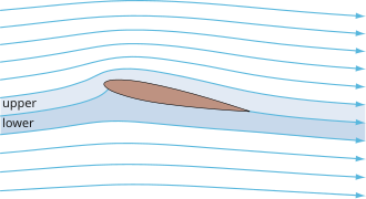
An airfoil consists of a suction surface (typically the upper side) and a pressure surface (typically the lower side). The difference in static pressure between these two surfaces is what generates the lift force.
Performance and Flow Behavior
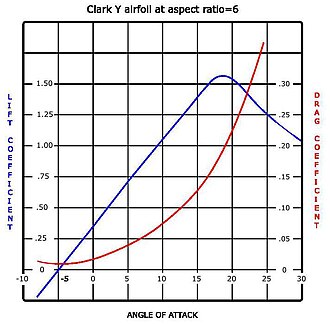
The relationship between the angle of attack and lift is generally linear until the airfoil reaches its stall point. At this critical angle—often around 18 degrees for certain profiles—the upper-surface boundary layer (the thin layer of fluid close to the surface) separates and thickens. This reduces the effective camber and increases pressure drag, leading to a rapid loss of lift.
Specialized Airfoil Designs
- Supercritical Airfoils: Designed for transonic speeds, these have maximum thickness closer to the leading edge to slowly transition supersonic flow back to subsonic speeds, reducing drag divergence.
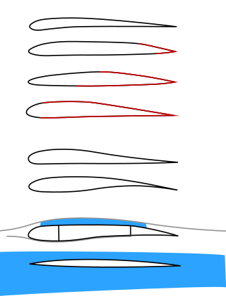
- Laminar Flow Airfoils: These move the maximum thickness point from the typical 25% chord position to 60% or more. This maintains smooth, non-turbulent flow over a larger area, significantly reducing drag. However, they are sensitive to surface contamination, such as insect impacts.
- Supersonic Airfoils: These are highly angular with sharp leading edges, making them very sensitive to changes in the angle of attack.
Thin Airfoil Theory
Developed in the 1920s by Max Munk and Hermann Glauert, Thin Airfoil Theory provides a mathematical basis for incompressible, inviscid (frictionless) flows. It idealizes the airfoil as a 1D blade with zero thickness and infinite wingspan.
Key theoretical findings include:
- For symmetric airfoils, the aerodynamic center and center of pressure both lie exactly one-quarter of the chord behind the leading edge.
- For cambered airfoils, the aerodynamic center remains at the quarter-chord point, but the center of pressure shifts as the angle of attack changes.
- The aerodynamic center is the point where the pitching moment remains independent of the lift coefficient.
Summary of Airfoil Characteristics
| Airfoil Type | Leading Edge Shape | Primary Use Case | Key Characteristic |
|---|---|---|---|
| Subsonic | Rounded | General Aviation | High lift at lower speeds |
| Supersonic | Sharp/Angular | High-speed jets | Reduced wave drag |
| Supercritical | Moderate | Transonic transports | Delayed drag divergence |
| Laminar Flow | Variable | Gliders/Modern jets | Reduced skin friction |
Frequently Asked Questions
What is the difference between an airfoil and a hydrofoil?
An airfoil is designed to operate in the air (a gas), while a hydrofoil is designed to operate in water (a liquid). Both use the same fundamental principles of fluid dynamics to generate lift.
What causes an airfoil to stall?
A stall occurs when the angle of attack increases to a point where the boundary layer on the upper surface separates from the airfoil. This disrupts the smooth flow of air, drastically increasing drag and causing a sudden loss of lift.
How does camber affect lift?
Camber refers to the asymmetry between the upper and lower surfaces of an airfoil. Unlike symmetric airfoils, cambered airfoils can generate lift even when the angle of attack is zero.
Why are laminar flow wings sensitive to insects?
Laminar flow requires a very smooth surface to prevent the boundary layer from becoming turbulent. Small imperfections, such as insects stuck to the wing, create disturbances that trigger turbulence, thereby increasing drag.
What is the significance of the quarter-chord point?
According to thin airfoil theory, the quarter-chord point (25% of the distance from the leading edge) is the location of the aerodynamic center, where the pitching moment remains constant regardless of changes in lift or angle of attack.