Servomechanisms: Principles, Applications, and Engineering Evolution
In the realms of mechanical and control engineering, a servomechanism (commonly referred to as a servo system or simply a servo) is a sophisticated control system designed to manage the position and time derivatives—such as velocity—of a mechanical system. Derived from the Latin word servus, meaning 'slave', these systems are engineered to follow precise commands with high accuracy.
At its core, a servomechanism utilizes closed-loop control to minimize steady-state error and optimize dynamic response. Unlike open-loop systems, closed-loop control employs error-sensing negative feedback to continuously correct the mechanism's action. In applications where displacement is critical, the system typically integrates an encoder or a similar feedback mechanism to ensure the output matches the desired target. The process of following a specific motion trajectory is known as servoing.
It is important to distinguish true servomechanisms from simple automated controls. For instance, a car's power window is not a servomechanism because it lacks automatic feedback; the human operator provides the feedback via observation. Conversely, a car's cruise control is a servomechanism because it uses closed-loop feedback to maintain a constant speed automatically.
Key Facts
- Core Function: Controls mechanical position, speed, and attitude using negative feedback.
- Feedback Loop: Compares actual output (via transducers) to the desired input to generate an error signal.
- Components: Typically consists of a controller, a power amplifier, a servomotor, and a feedback sensor (encoder or potentiometer).
- Versatility: Available in electric, hydraulic, and pneumatic configurations.
- Precision: Can achieve sub-micrometer accuracy, as seen in hard disk drive magnetic servo systems.
Types of Control and Applications
Position Control
Position control is the most common application of servos. These systems operate by comparing the control input to the actual position measured by a transducer. Any difference between the two creates an error signal, which is amplified and used to drive the motor in the direction required to eliminate the error, often utilizing an H-bridge controller. This can result in either linear or rotary (angular) output.
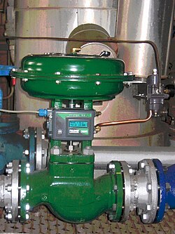
Speed Control
Servomechanisms are also used for speed regulation via governors. Historical examples include mechanical governors in steam engines and water wheels. In aviation, constant speed propellers were developed before World War II to manage engine speed during maneuvers, while modern gas turbine engines use electronic or hydromechanical fuel controls for governing.
Diverse Industrial and Commercial Uses
From military fire-control and marine navigation to modern consumer electronics, servomechanisms are ubiquitous. Key examples include:
- Aerospace: Fly-by-wire systems that actuate control surfaces and automatic navigation systems.
- Robotics and Models: Radio-controlled (RC) airplanes, boats, and small-scale robotics.
- Precision Tools: Automatic machine tools and satellite-tracking antennas.
- Consumer Tech: Autofocus lenses in cameras and high-precision head positioning in hard disk drives.

The Servomotor
A servomotor is a specialized motor paired with a rotary encoder or a potentiometer to create a functional servomechanism. The choice of feedback sensor determines the system's precision and stability:
- Potentiometers: Provide a simple analog signal. They are cost-effective but prone to drift during temperature changes. These are common in low-end RC servos.
- Encoders: Provide digital position and speed feedback. When paired with a PID controller (Proportional-Integral-Derivative), they allow for faster stabilization and higher precision. These are standard in high-end industrial components.
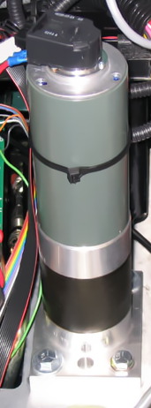
It is a common misconception that stepper motors are servomotors. While stepper motors provide angular positioning, they typically operate in an open-loop manner without feedback, making them suitable for medium-precision tasks rather than true servomechanism applications.
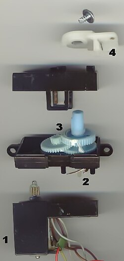
In RC servos, a microcontroller or receiver sends pulse-width modulation (PWM) signals. The internal electronics translate the pulse width into a target position, powering the motor until the potentiometer reaches the corresponding value.
Historical Evolution
The evolution of servomechanisms tracks the history of automation. James Watt's steam engine governor is widely regarded as the first powered feedback system. Early position control was pioneered in ship steering engines, with John McFarlane Gray's design used on the SS Great Eastern in 1866, and similar contributions by Joseph Farcot.
The late 19th and early 20th centuries saw the introduction of the telemotor (1872) and the Ragonnet power reverse mechanism (1909). Electrical servos emerged around 1888 with Elisha Gray's Telautograph. During World War II, the development of the amplidyne power amplifier significantly advanced electrical fire-control systems.
Modern systems have transitioned from vacuum tubes and early amplifiers to solid-state power amplifiers utilizing MOSFET or thyristor devices.
Performance Classifications
Servos are categorized by their feedback control systems into three primary types:
| Servo Type | Steady-State Output | Error Signal Characteristic |
|---|---|---|
| Type 0 | Constant value | Constant error signal |
| Type 1 | Constant value | Null error signal (constant error when tracking a changing reference) |
| Type 2 | Constant value | Null error signal (null error when tracking a changing reference) |
Additionally, the servo bandwidth is a critical metric, indicating how effectively the servo can follow rapid changes in the commanded input.
Frequently Asked Questions
What is the difference between a servo and a stepper motor?
A servo operates on a closed-loop system with feedback (via an encoder or potentiometer) to ensure the output reaches the desired position. A stepper motor generally operates in an open-loop manner, moving in fixed increments without verifying its actual position via feedback.
What is negative feedback in a servo system?
Negative feedback is the process of measuring the actual output of the system and subtracting it from the desired input. This creates an error signal that tells the motor which direction to move to correct the discrepancy, effectively "fighting" the error to bring it to zero.
What does PWM stand for in RC servos?
PWM stands for Pulse-Width Modulation. It is a method of encoding information in a signal by varying the width of electrical pulses, which the servo's internal circuitry interprets as a specific target position.
Why are encoders preferred over potentiometers in industrial servos?
Encoders are more stable and accurate than potentiometers, which can suffer from signal drift as temperatures change. Encoders also provide speed feedback, allowing for more precise control and faster stabilization when used with a PID controller.
What is a Type 2 servo?
A Type 2 servo is a high-performance system that can maintain a null error signal even when the reference input is changing at a constant rate. It only produces a constant error when the reference is accelerating.