NEMS Nanomotors: Engineering the First Nano-Scale Actuators
The transition from Microelectromechanical Systems (MEMS) to Nanoelectromechanical Systems (NEMS) has enabled the creation of machinery at an atomic scale. One of the most significant achievements in this field is the development of the first NEMS nanomotor, a device that functions as a scaled-down version of traditional micro-motors but operates using the unique properties of carbon nanotubes.
This nanoactuator features a gold plate rotor that rotates around the axis of a multi-walled nanotube (MWNT). The MWNT is anchored at both ends to a silicon dioxide (SiO2) layer, which serves as the electrodes. To control the motor, three fixed stator electrodes—two positioned in-plane and one gate stator buried beneath the surface—surround the rotor. By applying four independent voltage signals to the rotor and stators, engineers can precisely control the rotation's position, velocity, and direction. Empirical data shows these motors can achieve angular velocities of at least 17 Hz, with the potential for much higher frequencies.
Key Facts
- Rotor Material: Gold plate measuring 250–500 nm per side.
- Axis of Rotation: Multi-walled carbon nanotubes (MWNT).
- Minimum Velocity: 17 Hz during complete rotations.
- Actuation Method: Electrostatic actuation using asymmetrical sinusoidal voltages.
- Synthesis Method: Arc-discharge technique for high-quality MWNTs.
- Precision: Alignment achieved within 1° for nanotubes over 1 μm long.
Fabrication Process
Creating a nanomotor requires extreme precision and a multi-step fabrication sequence. MWNTs are synthesized via the arc-discharge technique, suspended in 1,2-dichlorobenzene, and deposited onto degenerately doped silicon substrates coated with 1 μm of SiO2. To ensure perfect placement, an Atomic Force Microscope (AFM) or Scanning Electron Microscope (SEM) is used to align the MWNT with pre-made substrate markings.
The rotor and stators are patterned using electron beam lithography. Gold is thermally evaporated with a chromium adhesion layer, lifted off in acetone, and annealed at 400 °C to optimize electrical and mechanical contact. To allow the rotor to spin freely, an HF etch removes 500 nm of the SiO2 substrate.
A primary challenge in fabrication is the high torsional spring constant (10 to 10 N m) of the MWNT, which resists angular displacement. To solve this, the outer shells of the MWNT are removed between the anchors and the rotor. This is achieved either by applying large stator voltages (~80 V DC) to cause mechanical fatigue or through Electrical Driven Vaporization (EDV), a variant of the electrical-breakdown technique that selectively removes the outermost shells to create a low-friction bearing.
Synthesis and Selection of Nanotubes
Arc-Discharge Evaporation Technique
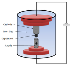
To produce high-quality MWNTs, the arc-discharge technique is employed. This process occurs in a reaction vessel filled with an inert gas (such as helium or argon) at a constant pressure. A potential of approximately 18 V is applied across a 6 mm anode and a 9 mm cathode, separated by 1–4 mm. With currents between 50–100 A, carbon atoms are ejected from the anode and deposit onto the cathode.
At a pressure of 500 torr, the yield peaks, converting 75% of the graphite rod into nanotubes. These nanotubes typically range from 2 to 20 nm in diameter and several micrometers in length. This method is preferred over laser ablation or chemical vapor deposition (CVD) because it results in fewer structural defects and superior electrical and thermal properties.
Electrical-Breakdown Technique
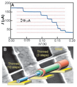
Since large-scale synthesis produces a mix of semiconducting and metallic nanotubes, the electrical-breakdown technique is used for selection. Carbon nanotubes can withstand current densities up to 10 A/cm. However, high currents cause the outermost shell to oxidize and fail. By applying an increased bias, the shells fail sequentially, resulting in discrete drops in conductance. This allows for the controlled removal of shells without disturbing the inner layers.
Scaling to Nanoactuator Arrays
Because a single nanoactuator produces a minuscule output, arrays are necessary for practical applications. While CVD allows for direct growth on substrates, it often produces lower-quality MWNTs and requires high temperatures that can damage other components. Instead, a targeting method is used: a silicon substrate is coated with a thin polymer layer and selectively exposed to a low-energy electron beam via an SEM to create adhesive zones.
For alignment, MWNTs are suspended in orthodichlorobenzene (ODCB) using ultrasonication. Drops of this suspension are pipetted onto a substrate rotating at 3000 rpm on a spin coater. This process ensures that 90% of nanotubes longer than 1 μm are aligned within 1°.
Operating Principles
The motor operates via electrostatic actuation. By applying out-of-phase sinusoidal voltages to the in-plane stators (S1 and S2), a doubled frequency signal to the gate stator (S3), and a DC offset to the rotor (R), the rotor plate is drawn toward successive stators. The voltages used are typically less than 5 V. The extreme proximity between the stators and the rotor allows for rotation with very little force, and reversing the bias reverses the direction of rotation.
| Parameter | Value/Detail |
|---|---|
| Rotor Dimensions | 250–500 nm (side) |
| MWNT Diameter | 2–20 nm |
| Operating Voltage | < 5 V (Actuation) / ~80 V (Shell removal) |
| Angular Velocity | ≥ 17 Hz |
| Alignment Precision | Within 1° (for > 1 μm tubes) |
| Intershell Spacing | 0.34 nm |
Potential Applications
- Optical Devices: The rotating plate can act as a mirror for ultra-high-density optical switching and sweeping.
- Telecommunications: Arrays of actuators can function as high-frequency mechanical filters for parallel signal processing.
- Fluidics and Biology: The plate can serve as a paddle for detecting fluid motion in microfluidics or as a bio-mechanical element in biological systems.
- Chemistry and Sensing: Use as a gated catalyst in wet chemistry or as a general sensor element.
- Electromagnetics: A charged oscillating plate can act as a transmitter of electromagnetic radiation.
Frequently Asked Questions
How does the NEMS nanomotor achieve rotation?
It uses electrostatic actuation, where asymmetrical sinusoidal voltages are applied to three stators and a DC offset is applied to the rotor, pulling the rotor plate in a sequential circular motion.
Why are the outer shells of the MWNT removed?
The original MWNT has a very high torsional spring constant that prevents large angular displacements. Removing outer shells reduces this stiffness, allowing the rotor to rotate more freely.
What is the advantage of the arc-discharge technique over CVD?
The arc-discharge technique produces nanotubes with fewer structural defects and better electrical, mechanical, and thermal properties due to the high growth temperatures involved.
How is the alignment of nanotubes ensured in arrays?
Alignment is achieved by pipetting an MWNT suspension onto a substrate rotating at 3000 rpm, using centrifugal force to align the tubes within 1°.
What is the role of the electrical-breakdown technique?
It is used to separate and select specific types of nanotubes (metallic vs. semiconducting) by sequentially removing carbon shells through controlled oxidation via high current densities.