Interference Fringes: Measuring Surface Flatness with Optical Flats
In high-precision engineering, determining whether a surface is perfectly flat requires tools far more sensitive than a standard ruler. One of the most effective methods involves the use of an optical flat—a high-quality glass disk with an extremely precise surface. By observing how light interacts between this flat and a test piece, technicians can visualize microscopic deviations in height through a phenomenon known as interference fringes.
How Interference Fringes Form
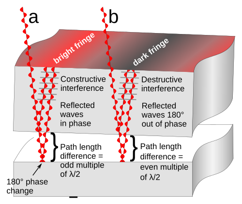
When an optical flat is placed upon a surface to be tested, a microscopic gap typically exists between the two, unless the surfaces are perfectly matched. To analyze this gap, monochromatic light (light of a single wavelength, such as red light) is shone through the glass flat. This light reflects from two distinct points: the bottom surface of the optical flat and the top surface of the test piece.
These two reflected rays combine and superpose. However, they do not travel the same distance; the ray reflecting off the bottom surface travels an additional path length equal to twice the gap between the surfaces. Furthermore, the ray reflecting off the bottom surface undergoes a 180° phase reversal, whereas the internal reflection from the underside of the optical flat does not. The resulting brightness depends on the path length difference between these two rays.
Constructive vs. Destructive Interference
The interaction of these waves creates two distinct visual outcomes:
- Constructive Interference: This occurs when the path length difference is an odd multiple of half a wavelength (λ/2). In this state, the peaks and troughs of the waves coincide, reinforcing each other to create a bright area.
- Destructive Interference: This occurs when the path length difference is an even multiple of a half-wavelength. Here, the waves are 180° out of phase, meaning a peak coincides with a trough, canceling each other out to create a dark area.
If the gap between the surfaces varies, these bright and dark bands—called interference fringes—appear. Much like contour lines on a topographic map, these fringes reveal the height differences of the test surface. Because the wavelength of light is so small, this method is incredibly precise. For red light with a wavelength of approximately 700 nm, the height difference between two fringes is only 350 nm, which is roughly 1/100 the diameter of a human hair.
Key Facts
- Measurement Precision: The difference in gap height between two adjacent fringes is equal to one-half the wavelength (λ/2) of the light used.
- Phase Shift: A 180° phase reversal occurs at the reflection from the bottom surface, affecting the interference pattern.
- Visual Representation: Fringes act as contour lines; the gap between surfaces is constant along any single fringe.
- Example Scale: Using red light (λ ≈ 700 nm), the height difference between fringes is approximately 350 nm.
Mathematical Derivation
The variation in brightness can be modeled by summing the electric fields of the two reflected waves. If we assume both rays have the same intensity (A), the first ray is represented as:
E1(z, t) = A cos(2πz/λ − ωt)
The second ray, delayed by the path length and the 180° phase reversal, introduces a phase shift (φ):
E2(z, t) = A cos(2πz/λ − ωt + φ)
The total electric field (E) is the sum of these two waves. Using trigonometric identities, the resulting amplitude is proportional to the cosine of φ/2. The phase difference φ is calculated as the sum of the path length difference (2d) and the reflection phase shift:
φ = 4πd/λ + π = 2π(2d/λ + 1/2)
Conditions for Brightness and Darkness
Based on this derivation, we can determine the exact gap width (d) for the fringes:
- Maximum Brightness (Constructive): Occurs when d = λ/4, 3λ/4, 5λ/4, etc.
- Minimum Brightness (Destructive): Occurs when d = 0, 2λ/4, 4λ/4, 6λ/4, etc.
This confirms that the separation between two adjacent bright or dark fringes represents a change in the gap length of exactly one-half wavelength (λ/2).
| Interference Type | Phase Relationship | Visual Result | Gap Width (d) Examples |
|---|---|---|---|
| Constructive | In Phase | Bright Fringe | λ/4, 3λ/4, 5λ/4 |
| Destructive | 180° Out of Phase | Dark Fringe | 0, λ/2, λ |
Frequently Asked Questions
What is an optical flat?
An optical flat is a precision-ground glass disk used as a reference surface to measure the flatness of other surfaces through the observation of light interference.
Why is monochromatic light used in this process?
Monochromatic light consists of a single wavelength. This ensures that the interference fringes are distinct and clear; using white light (which contains many wavelengths) would cause the fringes to overlap and blur.
What does a single fringe represent on the test surface?
A single fringe represents a line of constant gap width between the optical flat and the test surface, similar to how a contour line on a map represents a constant elevation.
How sensitive is this measurement technique?
It is extremely sensitive. Because it relies on the wavelength of light, it can detect height variations as small as half a wavelength (e.g., 350 nm for red light), which is significantly smaller than the width of a human hair.
What causes the 180° phase reversal?
The phase reversal occurs when light reflects off the bottom surface (the test piece), which is a reflection from a medium of different refractive index, shifting the wave's phase by half a cycle.